
Interfacing 7-Seg Display to Microcontroller
|
7 Seg displays are are basically 7 LED's. It will be much easier to understand if you first read Interfacing LED's to Microcontroller. |
||||||||||||||||
|
|
||||||||||||||||
|
||||||||||||||||
|
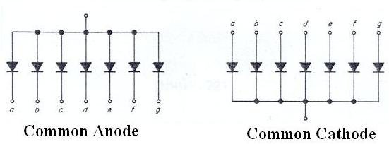
Basically there are two types of 7-Seg display's:
|
||||||||||||||||
|
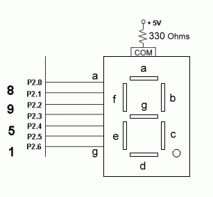
Here we will be only discussing the Common Anode type.In common Anode in order to turn ON a segment the corresponding pin must be set to 0. And to turn it OFF it is set to 1. |
||||||||||||||||
|
||||||||||||||||
|
||||||||||||||||
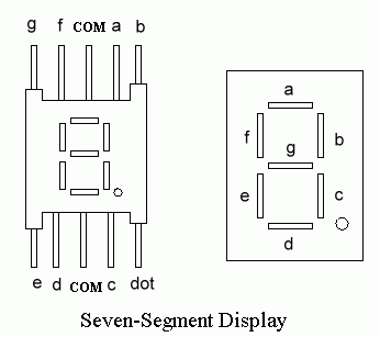
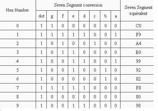
| Figure 1 shows how to interface 7-seg display to a microcontroller. Now we create a lookup table containing the seven segment pattern to display the corresponding hex digits. e.g. consider we have to display '1' from the above figure we come to know that turning ON segment B & C will show '1' on the 7-seg display so P2.1 & P2.2 should be LOGIC 0 whereas rest of the pins should be LOGIC 1. FIGURE 2 shows the lookup table for CA display. | ||||||||||||||||
|
||||||||||||||||
|
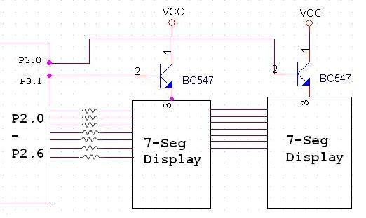
We can now interface a single 7-Seg to the microcontroller but for interfacing multiple 7-seg's we use Scanning Principle where One 7-seg is displayed after another but this process is very fast hence the flickering cannot be seen by human eye. Figure 3 shows the circuit for interfacing two 7 seg displays. |
||||||||||||||||
 |
||||||||||||||||
|
When interfacing more than one 7-seg display the segment's (A-G) of all displays are connected together whereas their ANODE (Cathode in case of CC displays) are switched ON one after another. Consider we have to display '31' on the above 7-seg display so we TURN ON the first transistor by setting its corresponding pin to 1 & then give the 7-seg equivalent code for '3' which is 4fh. Then we TURN OFF the first transistor & TURN ON the second & output its corresponding 7-seg equivalent code of '1' i.e. 06h.Then we again go back to display '3' this is a never ending loop. |
||||||||||||||||
|
ORG 0000h CLR P3.0 CLR P3.1 MOV P2,#0ffh loop: SETB P3.1 MOV P2,#4fh CALL delay CLR P3.1 SETB P3.0 mov P2,#06h CALL delay AJMP loop |
.